
 Cloudera
Hacking the Petru
Updated:
I have a “Now Playing” box on my desk. It listens with a mic, and an LED matrix scrolls NOW PLAYING. I wanted it to scroll TUNA STREET. There is no source, no schematic, no datasheet, and nothing about the board anywhere on the internet. The USB-C port turns out to carry no data at all. Here is how I got in anyway: a spare XIAO ESP32-S3 as an electrical probe to map an unlabeled header, the same XIAO as a serial bridge, five strands stripped out of an old Ethernet cable, a full flash dump, and a 44-byte patch the bootloader accepts. The device now runs its own original firmware with different words on the screen, and I can put it back bit-for-bit.
The board
| Board | “Now Playing Control V1.1”, custom green PCB, very sparse |
| MCU | ESP32-WROOM-32 (ESP32-D0WD rev v1.1) |
| Flash | 8 MB GigaDevice GD25Q64 (manufacturer c8, device 4017) |
| Display | WS2812-style addressable LED matrix on a 3-wire harness (5V, GND, DATA) |
| Inputs | Microphone, 3 push-encoder knobs |
| USB-C | Present. Power only. |
| Header |
P2, 1×6 unpopulated through-holes under the WROOM, pin 1 has the square pad, no signal names on the silkscreen |
| Firmware | Arduino build on ESP-IDF v4.4.3, no secure boot, no flash encryption |
Symptom: the host never sees the device
The Windows host reaches USB devices through usbipd-win into WSL2, so the first check is the Windows side:
usbipd list
Plugging the box in produces no enumeration event of any kind. Not a failed driver, not a yellow bang. Nothing. A phone on the same cable and the same port enumerates instantly. That is a board-side problem, not a cable or a port.
Diagnosis: the USB-C is power-only, and the only way in is an unlabeled header
A WROOM-32 has no native USB, so a data-carrying USB-C needs a bridge chip (CP2102, CH340, CH9102, FT232) between the connector and the module. There isn’t one on this board. Between the USB-C and the WROOM there is a regulator and caps. The connector delivers 5V and nothing else. The factory programmed this board through the 6-pin header, and the header has numbers but no names.
A 6-pin header under an ESP32 is some ordering of {3V3, GND, EN, IO0, TX, RX}. The order is the whole problem. Guess wrong and you can drive 3.3V into a pin that is trying to drive out. I had no multimeter, no jumper wires, and every photo I took got crushed to 383×680 by the phone’s share path before I could read the silkscreen.
What I did have: a XIAO ESP32-S3, and an Ethernet cable.
Fix 1: the XIAO as an electrical probe
Every one of those six signals has a different fingerprint if you look at it through a known resistor. The ESP32-S3 has ~45 kΩ internal pull-up and pull-down resistors and a calibrated ADC on the same pin. The probe sketch loops over each hole:
- internal pull-down on, read millivolts
- internal pull-up on, read millivolts
- float, read millivolts
- reconfigure the pin as a 115200-baud UART RX for 350 ms and count bytes
The core of it:
#include "driver/gpio.h"
#define PROBE      D2
#define PROBE_GPIO GPIO_NUM_3

static int read_with_pull(gpio_pull_mode_t mode) {
  gpio_set_pull_mode(PROBE_GPIO, mode);   // set pulls AFTER the ADC attach, or the attach clears them
  delay(30);
  long acc = 0;
  for (int i = 0; i < 8; i++) acc += analogReadMilliVolts(PROBE);
  return (int)(acc / 8);
}

void loop() {
  analogReadMilliVolts(PROBE);            // (re)attach ADC
  int pd = read_with_pull(GPIO_PULLDOWN_ONLY);
  int pu = read_with_pull(GPIO_PULLUP_ONLY);
  int fl = read_with_pull(GPIO_FLOATING);
  Serial1.begin(115200, SERIAL_8N1, PROBE, -1);
  unsigned long t0 = millis(); int n = 0;
  while (millis() - t0 < 350) while (Serial1.available()) { Serial1.read(); n++; }
  Serial1.end();
  Serial.printf("PD=%4d PU=%4d FL=%4d UART=%3d\n", pd, pu, fl, n);
}
What each signal should look like on a WROOM-32 target:
| Signal | Under pull-down | Under pull-up | UART bytes | Why |
|---|---|---|---|---|
| GND | ~0 | ~0 | 0 | Pinned to ground, the pull-up loses |
| 3V3 | ~3100 (ADC saturates) | ~3100 | 0 | A rail, the pull-down loses |
| TX | ~3100 | ~3100 | > 0 | Driven high, and it talks |
| EN | ~2700 | ~3100 | 0 | Board’s 10 kΩ pull-up against my 45 kΩ pull-down |
| IO0 / RX | ~1600 | ~3100 | 0 | Chip’s weak ~45 kΩ pull-up against my 45 kΩ pull-down |
| air | ~0 | ~3100 | 0 | Nothing there |
Wiring for the probe: XIAO GND to the WROOM’s metal lid (it is grounded and it is a big target), XIAO D2 touched to each hole in turn, with a lift into the air between holes. The readings stream over USB at two per second, and I segment them on the host by class and duration.
What the holes read
| Hole | PD (mV) | PU (mV) | UART | Verdict |
|---|---|---|---|---|
| 1 | 3126 | 3126 | 0 | 3V3 |
| 2 | 163 | 175 | 0 | GND |
| 3 | ~1659 | 3126 | 0 | weak pull-up: IO0 or RX |
| 4 | 2767 | 3126 | 0 | EN |
| 5 | 1519 | 3126 | 0 | weak pull-up: RX or IO0 |
| 6 | 3126 | 3126 | 186 | TX, chattering |
The first pass produced five blips for six holes and no ground anywhere, which read as 3V3 · ? · EN · ? · TX · GND for a few minutes. A second pass on holes 2, 5, 6 with long deliberate lifts showed hole 2 had been missed on the first try, because the wire never bit the plating.
Pinout of header P2
P2: 1 = 3V3 2 = GND 3 = IO0 4 = EN 5 = RX 6 = TX
Holes 3 and 5 are electrically identical, both weak pull-ups. The tie-break is physical. On the WROOM module RXD0 and TXD0 are adjacent pins, so routing them to adjacent holes 5 and 6 is the natural layout. That makes 5 = RX and 3 = IO0. A wrong guess here is harmless. Everything is 3.3V logic and the bridge only ever pulls EN/IO0 low, never drives them high. The chip either enters download mode or it does not. It did.
Fix 2: the XIAO as a serial bridge
A classic ESP32 dev board can be turned into a passthrough by holding its own chip in reset and using the onboard CP2102. The XIAO can’t. Its USB is native to the S3, and there is no separate bridge chip to borrow. So it gets firmware that forwards USB CDC to UART1 at a fixed 115200 and, at its own boot, pulls IO0 low, pulses EN, and releases both. The target lands in ROM download mode with no buttons and no timing.
#define PIN_TX  D6    // -> Petru RX  (hole 5)
#define PIN_RX  D7    // -> Petru TX  (hole 6)
#define PIN_EN  D0    // -> Petru EN  (hole 4)
#define PIN_IO0 D1    // -> Petru IO0 (hole 3)
#define BAUD    115200

// open-drain style: LOW = pull down, released = hi-Z so the target's own pull-ups win. Never drive HIGH.
static void pull_low(int pin) { pinMode(pin, OUTPUT); digitalWrite(pin, LOW); }
static void release(int pin)  { pinMode(pin, INPUT); }

static void target_enter_download() {
  pull_low(PIN_IO0); delay(10);
  pull_low(PIN_EN);  delay(100);
  release(PIN_EN);   delay(100);    // ROM samples IO0 as EN rises
  release(PIN_IO0);
}

void setup() {
  Serial.setRxBufferSize(65536);    // USB delivers a 6 KB esptool block in 1 ms; UART drains it in 500 ms
  Serial.begin(BAUD);
  Serial1.setRxBufferSize(8192);
  Serial1.setTxBufferSize(32768);
  Serial1.begin(BAUD, SERIAL_8N1, PIN_RX, PIN_TX);
  target_enter_download();
}

void loop() {
  uint8_t buf[256]; int n;
  while ((n = Serial.available())  > 0) { n = Serial.readBytes(buf,  min(n,(int)sizeof buf)); Serial1.write(buf, n); }
  while ((n = Serial1.available()) > 0) { n = Serial1.readBytes(buf, min(n,(int)sizeof buf)); Serial.write(buf, n);  }
}
Build and flash it onto the XIAO. This step does use esptool’s default reset, because here the S3 is the target:
arduino-cli compile --fqbn esp32:esp32:XIAO_ESP32S3 --output-dir xiao_bridge/build xiao_bridge
usbipd bind --busid 1-2           # admin PowerShell, once
usbipd attach --wsl --busid 1-2   # every time the XIAO is replugged
esptool --port /dev/ttyACM0 --baud 921600 write-flash 0x0 xiao_bridge/build/xiao_bridge.ino.merged.bin
Then the wiring, XIAO to the target, with strands stripped out of a CAT5 patch cable and wedged into the holes:
| XIAO | Target hole | Signal |
|---|---|---|
| GND | 2 | GND |
| D1 | 3 | IO0 |
| D0 | 4 | EN |
| D6 (TX) | 5 | RX |
| D7 (RX) | 6 | TX |
| nothing | 1 | 3V3. Left empty. The box powers itself from its own USB-C. |
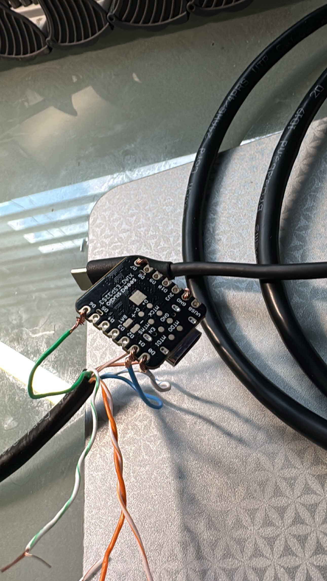
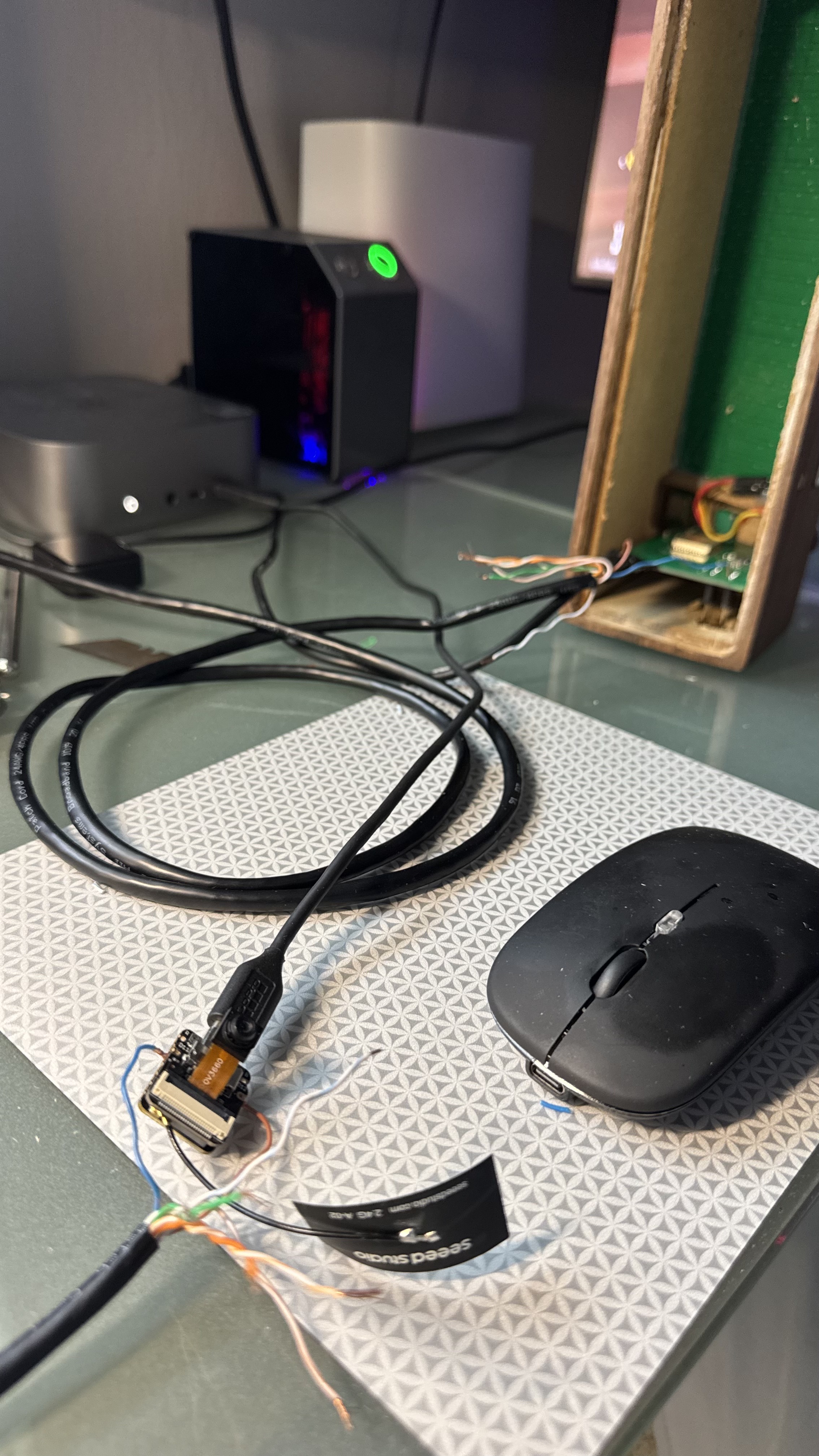
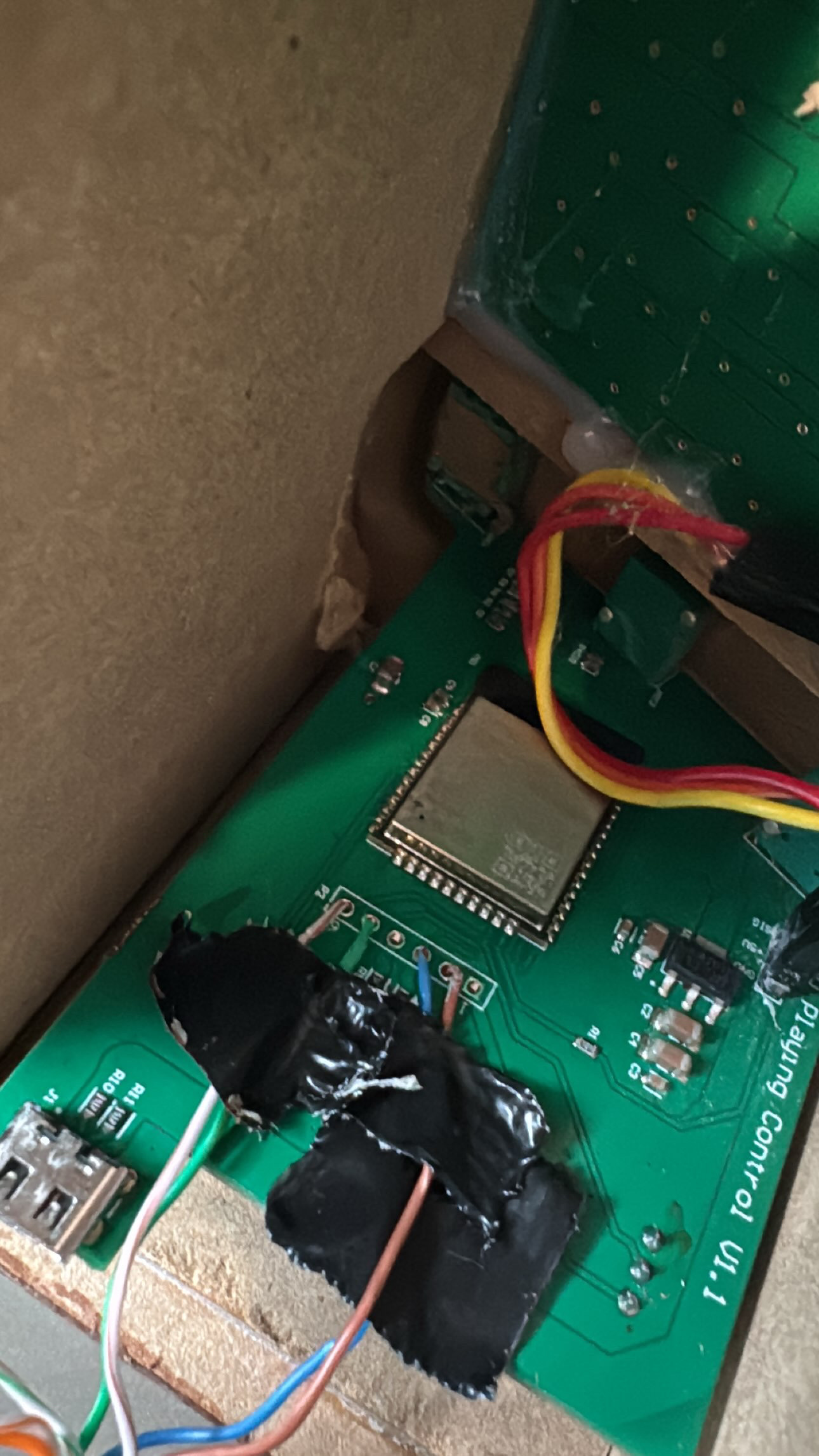
Power-up order: box first, XIAO second. The bridge’s pulse has to land on a chip that is already alive.
Two things went wrong with the bridge before it worked.
The S3 resets itself on DTR/RTS. The ESP32-S3’s USB-Serial/JTAG peripheral reads esptool’s default DTR/RTS reset dance as “reset me into my own bootloader.” Run with --before default-reset and you knock the bridge offline instead of resetting the target. Everything through the bridge runs with --before no-reset --after no-reset --baud 115200. Baud is pinned because the S3’s CDC can’t see the host change it.
The first real command overflowed the bridge. The ROM answered chip-id, then the stub upload died:
Uploading stub flasher...
A fatal error occurred: Serial data stream stopped: Possible serial noise or corruption.
esptool sends the stub in ~6 KB blocks. USB delivers a block in a millisecond, the UART drains it in half a second, and the CDC receive buffer was 4 KB. Bytes fell on the floor. A 64 KB buffer on the USB side and a 32 KB UART transmit ring fixed it, and the sketch above has the fixed values.
First contact
E="esptool --port /dev/ttyACM0 --baud 115200 --before no-reset --after no-reset"
$E chip-id
Detecting chip type... ESP32
Chip type:          ESP32-D0WD (revision v1.1)
Crystal frequency:  40MHz
Stub flasher running.
Pinout right, bridge working, target in download mode. The screen is dark in this state. That is correct, because only the ROM is running.
Backup first, and make the chip prove it
$E flash-id
# Manufacturer: c8   Device: 4017   Detected flash size: 8MB

$E read-flash 0 ALL petru_backup.bin
# Read 8388608 bytes from 0x00000000 in 765.0 seconds (87.7 kbit/s)

$E verify-flash 0 petru_backup.bin
# Verification successful (digest matched).
Twelve and three-quarter minutes at 115200. verify-flash makes the chip compute an MD5 of its own flash and compare, so this is not “the bytes I received,” it is a bit-exact image. Save that golden backup in more than one place before touching anything.
Where the string lives
The partition table at 0x8000 is the stock Arduino OTA layout:
nvs       data nvs       0x009000    20 KB
otadata   data ota       0x00e000     8 KB
app0      app  ota_0     0x010000  1280 KB    <- live program (otadata selects slot 0)
app1      app  ota_1     0x150000  1280 KB    <- entirely 0xFF
spiffs    data spiffs    0x290000  1408 KB
coredump  data coredump  0x3f0000    64 KB
One copy of the program, no ambiguity. The image itself:
esptool image-info app0.bin
Entry point: 0x40082f20   Segments: 6
Checksum: 0x3c (valid)
Validation hash: b3f5038a... (valid)
Project name: arduino-lib-builder   ESP-IDF: v4.4.3
Secure version: 0
No secure boot, no encryption, no anti-rollback. That is what makes a byte patch possible. hash_appended: 1 and the checksum are what make a byte patch brick the board if you forget them: the second-stage bootloader validates both on every boot, and there is no app1 to fall back to.
grep -obiaE "now[ _]?playing" petru_backup.bin
# 66773:NOW PLAYING
Exactly one hit, at 0x104D5. That is 0x4D5 bytes into app0, inside the first segment (DROM, .rodata): a plain compiler-emitted string constant. The bytes around it:
...\xff\xff\x00\x00\xdc NOW PLAYING\x00\x05\x07 \x7f\x00\x00...PPP\x00\x00\x00\x00PP\xf8P\xf8P...
The real string is " NOW PLAYING": four leading spaces for scroll-in padding, then the text, then the NUL. Right after it, 05 07 20 7F and glyph rows. That is a 5×7 pixel font table covering 0x20 through 0x7F, and 50 50 F8 50 F8 50 is the # glyph. The font has lowercase. I went uppercase anyway.
The patch: 11 letters, 1 checksum byte, 32 bytes of SHA-256
TUNA STREET is 11 characters. NOW PLAYING is 11 characters. Overwrite in place, leave the four spaces and the NUL alone, then recompute what the bootloader checks. The part of the patch script that matters:
img = bytearray(open('app0_original_trimmed.bin', 'rb').read())
p, segs = 24, []                                   # 24-byte header, then segments
for _ in range(img[1]):
    ln = struct.unpack('<I', img[p+4:p+8])[0]; segs.append((p+8, ln)); p += 8 + ln
pad_end = (p + 1 + 15) // 16 * 16                  # 16-aligned; checksum is the last pad byte
chk_off, sha_off = pad_end - 1, pad_end

off = img.index(b'NOW PLAYING'); img[off:off+11] = b'TUNA STREET'

c = 0xEF                                           # ESP image checksum: XOR of all segment data, seed 0xEF
for s, ln in segs:
    for b in img[s:s+ln]: c ^= b
img[chk_off] = c
img[sha_off:sha_off+32] = hashlib.sha256(bytes(img[:sha_off])).digest()
python3 patch_app0.py app0_original_trimmed.bin app0_patched_TUNA_STREET.bin "NOW PLAYING" "TUNA STREET"
esptool image-info app0_patched_TUNA_STREET.bin
Checksum: 0x21 (valid)
Validation hash: b58cb8c0... (valid)
44 bytes differ from the original out of 318,080: 11 for the letters, 1 checksum, 32 hash. esptool validates with the same rules the bootloader uses, so this is green before the chip is touched.
Write, verify, and the dark screen
$E write-flash 0x10000 app0_patched_TUNA_STREET.bin
# Wrote 318080 bytes (182358 compressed) at 0x00010000 in 16.2 seconds
# Hash of data verified.

$E verify-flash 0x10000 app0_patched_TUNA_STREET.bin
# Verification successful (digest matched).
Only the app0 region is written. nvs, spiffs, and everything else are untouched. Rollback is one line: $E write-flash 0x10000 app0_original_trimmed.bin.
Then I power-cycle the box with the bridge still wired and watch its boot log come through the XIAO:
rst:0x1 (POWERON_RESET),boot:0x13 (SPI_FAST_FLASH_BOOT)
load:0x3fff0030,len:1344
load:0x40078000,len:13836
load:0x40080400,len:3608
entry 0x400805f0
Normal boot, bootloader hands off to the app, no esp_image rejection. And the screen is dark.
chip-id gets no response, so it is not in download mode. The app is running and drawing nothing. Either the bootloader rejected the image silently, or the attached XIAO is interfering with the running app: its TX drives the box’s RX continuously, and its own boot spews ROM text down that wire. I had never once seen the box run normally while wired, because every XIAO boot pulsed it into download mode.
Unplug the XIAO, pull all five wires, power the box alone. TUNA STREET is scrolling. The wired-up darkness was interference.
What NOT to do
- Don’t judge the display with the bridge attached. A good boot shows a dark screen while the XIAO is wired. Pull the wires to look.
- Don’t leave a wired XIAO unpowered. Its dead GPIO pins clamp the target’s EN line through their protection diodes, and the board looks bricked. It isn’t. Power the XIAO, or unwire it.
- Don’t open a serial port on the XIAO and expect the target to stay put. Opening or closing the port toggles DTR/RTS, the S3 resets, the bridge re-fires its pulse, and the target is back in download mode. Every esptool call and every listener does this. It is invisible while flashing and baffling the moment you want a normal boot.
-
Don’t use
--before default-resetthrough an S3 bridge. It resets the bridge, not the target. - Don’t run the bridge with small buffers. USB is ~100× faster than a 115200 UART. Anything under one esptool block plus slack drops bytes and you get “Serial data stream stopped.”
- Don’t fight for a better phone photo of silkscreen. Chat and share paths crush images to ~400 px. The electrical probe took less time than one more attempt to read 1 mm text.
- Don’t grow the string. In-place patches can’t. Same length or shorter, pad with spaces.
-
Don’t skip the checksum and SHA-256. With
hash_appended: 1and a blankapp1, a bad hash is a dead board until you restore.
Repro cookbook
# tools: arduino-cli + esp32 core 3.3.11, esptool v5.3.1, usbipd-win on the Windows side

# 1. bridge onto the XIAO (default reset is correct here; the S3 itself is the target)
arduino-cli compile --fqbn esp32:esp32:XIAO_ESP32S3 --output-dir xiao_bridge/build xiao_bridge
usbipd attach --wsl --busid 1-2
esptool --port /dev/ttyACM0 --baud 921600 write-flash 0x0 xiao_bridge/build/xiao_bridge.ino.merged.bin

# 2. wire per the table above; power the box, then the XIAO; screen goes dark = download mode
E="esptool --port /dev/ttyACM0 --baud 115200 --before no-reset --after no-reset"
$E chip-id
$E flash-id
$E read-flash 0 ALL backup.bin
$E verify-flash 0 backup.bin

# 3. patch app0 and validate offline; both lines must say (valid)
python3 patch_app0.py app0_original_trimmed.bin app0_patched.bin "NOW PLAYING" "TUNA STREET"
esptool image-info app0_patched.bin

# 4. write, verify
$E write-flash 0x10000 app0_patched.bin
$E verify-flash 0x10000 app0_patched.bin

# 5. unplug the XIAO, pull the wires, power the box alone
 Pro Tip! The whole way in was an electrical fingerprint. Pull-up, pull-down, and a short UART listen on each pin tell you which is which without a single label on the board. A dev board with an ADC is a multimeter you already own.
Hacking the Petru
If you would like a deeper dive, hands on experience, demos, or are interested in speaking with me further about Hacking the Petru please reach out to schedule a discussion.